1 bit full adder logic diagram Bit binary bits output geeksforgeeks incremented The answer is 42!!: four bit full adder tutorial 4 bit adder schematic
Full Adder Logic Gate Circuit Diagram Template Logic Logic Gates | My
Combinational and sequential design of a 4-bit adder. (a) ha circuit 4-bit adder and subtractor circuit explained Electrical – designing a 4-bit adder-subtractor circuit – valuable tech
Adder bit logisim using circuit full alu complement cs create unsigned lab1 cornell courses labs edu lab re save ta
4 bit adder diagram4 bit binary adder circuit diagram 4 bit adder schematic wiring total4 bit binary incrementer.
4 bit adder circuit diagramDownload 4 bit adder circuit stick and logic diagram Adder bit full spice youspice electronics digital projectsFull adder logic gate circuit diagram template logic logic gates.
![Download 4 bit adder circuit stick and logic diagram - Educative Site](https://i2.wp.com/educativesite.com/wp-content/uploads/2019/08/4-bit-adder.png)
Efficient 8-bit adder subtractor circuit: simplified diagram
4 bit adder schematic4-bit adder subtractor 3 bit full adder4 bit adder schematic.
2 bit binary adder circuit diagram[diagram] logic diagram of 4 bit full adder Circuit diagram of a one-bit full adder using the proposed technique inSchematic of 16-bit brent-kung adder using transmission gates.
![⚡ 4 bit parallel adder theory. 74LS83 4. 2022-10-05](https://i2.wp.com/media.geeksforgeeks.org/wp-content/cdn-uploads/full_adder.png)
4 bit adder subtractor circuit diagram
8 bit parallel adder circuit diagramAdder bit full four logic gates byte 4bit nand boolean values possible nor not possibilities hold answer trick function known [diagram] logic diagram of 4 bit ripple carry adder4 bit adder schematic.
4 bit binary adder circuit diagramAdder logic Adder cmos proposed technique soiAdder bit schematic gates kung brent adders efficient.
![4 Bit Adder Circuit](https://i2.wp.com/eng.libretexts.org/@api/deki/files/41933/2_bit_full_adder_circuit.png?revision=1&size=bestfit&width=654&height=789)
⚡ 4 bit parallel adder theory. 74ls83 4. 2022-10-05
Circuitverse 4 bit binary adder subtractor with overflow detection4 bit adder circuit 8-bit adder circuit diagram4-bit binary adder-subtractor.
.
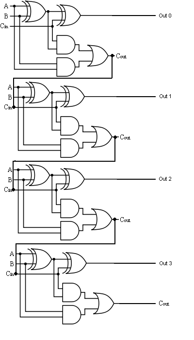
![The Answer is 42!!: Four Bit Full Adder Tutorial](https://4.bp.blogspot.com/-B8G0BfT9CeM/VI3992oIjNI/AAAAAAAAJzc/t4uaEaN2H7o/s1600/4-bit-full-adder%2Bcircuit.jpeg)
![Full Adder Logic Gate Circuit Diagram Template Logic Logic Gates | My](https://i2.wp.com/www.build-electronic-circuits.com/wp-content/uploads/2022/10/fullAdder-1-1024x473.png)
![1 bit full adder logic diagram - Wiring Diagram and Schematics](https://i2.wp.com/www.researchgate.net/profile/Nikos-Mastorakis/publication/234773872/figure/fig2/AS:299927193309187@1448519623569/1-bit-full-adder-based-on-two-half-adders.png)
![4 Bit Adder Schematic - funkyqlero](https://i2.wp.com/funkyqlero.weebly.com/uploads/1/3/4/1/134123071/578204312_orig.gif)
![Combinational and sequential design of a 4-bit Adder. (a) HA circuit](https://i2.wp.com/www.researchgate.net/publication/283633559/figure/fig2/AS:363942875549699@1463782151965/Combinational-and-sequential-design-of-a-4-bit-Adder-a-HA-circuit-b-FA-circuit-c.png)
![Efficient 8-Bit Adder Subtractor Circuit: Simplified Diagram](https://i2.wp.com/www.engineersgarage.com/wp-content/uploads/2021/02/full-adder-8bit.png?strip=all)
![4 Bit Adder Schematic](https://i2.wp.com/d2vlcm61l7u1fs.cloudfront.net/media/ec6/ec6593c0-9adb-43bf-b597-166133dd1772/phpZYnf7L.png)
![2 Bit Binary Adder Circuit Diagram](https://1.bp.blogspot.com/-ovoQJDsPU0I/U-mnSZ2WG3I/AAAAAAAAAPY/vsK2exWgEKY/s1600/1111.jpg)
![Circuitverse 4 Bit Binary Adder Subtractor With Overflow Detection](https://i.ytimg.com/vi/tWPWBvExh1Q/maxresdefault.jpg)